Background
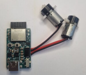
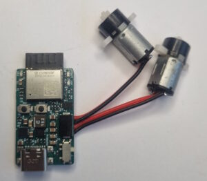
One of the main requirements for this project was physical size. I wanted the complete controller to fit on a small PCB, with every component mounted on the same side. This allows the finished board to be attached directly to a small LiPo battery using double-sided tape, creating a very compact unit with minimal wiring.
Instead of combining an ESP32 development board, motor-driver module, charger and voltage regulator, I integrated all these functions onto one purpose-built PCB.
Controller and wireless communication
The board is based on an ESP32-C6-MINI-1. It provides the processing power and wireless communication needed to control the car without a separate radio receiver or onboard computer.
Firmware can be developed using the Arduino framework and programmed directly through the board’s USB-C connector. The ESP32-C6 provides native USB Serial/JTAG support, so no separate USB-to-UART converter is required.
Motor control
The motors are controlled by a DRV8835 dual H-bridge driver. It can drive two brushed DC motors independently and provides bidirectional speed control using PWM and direction signals from the ESP32.
The DRV8835 was selected mainly because of its small package and because it does not require external power MOSFETs. Both points were important when trying to keep the PCB as small as possible.
Motor currents change quickly during startup, braking and direction changes. The high-current paths between the battery, motor driver and motor connectors therefore need to be short and wide. Local capacitors close to the DRV8835 help supply these current pulses and reduce disturbances elsewhere on the board.
Battery charging
Battery charging is handled by a BQ24075, designed for single-cell Li-ion and LiPo batteries. It includes power-path management, allowing the USB supply to power the electronics while also charging the battery.
The charge current and USB input-current limit can be configured to match the selected battery and power source. The charge current must be selected according to the battery capacity and its specified charging rate.
The USB-C connector is used for both programming and charging, which reduces the number of connectors needed on the PCB.
Power supply
A single-cell LiPo battery varies from approximately 4.2 V when fully charged to around 3 V when discharged. Because this range crosses the 3.3 V supply required by the ESP32, I used a TPS63070 buck-boost converter.
The TPS63070 steps the voltage down when the battery voltage is above 3.3 V and boosts it when the voltage falls below 3.3 V. This provides a stable supply for the ESP32 throughout most of the battery’s usable range.
The regulator’s power-good output is connected to an LED. This gives a simple indication that the 3.3 V rail is present and within regulation, which is useful during testing and debugging.
PCB layout and mechanical design
Fitting the charger, switching regulator, motor driver, USB interface and ESP32 onto a small single-sided assembly was one of the main challenges.
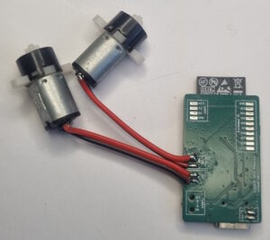
All components are placed on the same side of the PCB. The back of the board is therefore flat, allowing it to be mounted directly onto the LiPo battery or another flat surface. This arrangement also simplifies assembly and makes the complete controller-and-battery package easier to install inside a small RC car.
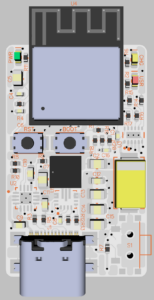
The compact layout does introduce some compromises. The motor driver carries relatively high currents and generates electrical noise, while the ESP32 needs a clean 3.3 V supply and a clear antenna area. The motor-current paths were kept as short as possible and routed away from the regulator feedback circuit, ESP32 and antenna.
Decoupling capacitors were placed close to each device, with additional bulk capacitance near the motor driver. The ground layout was arranged so that motor current does not share sensitive return paths used by the ESP32 or the regulator feedback network.
The ESP32 antenna also requires a keep-out area without copper or components. Mounting the PCB directly against a battery can affect antenna performance, particularly if the battery contains metallic foil. The antenna end of the PCB should therefore extend beyond the edge of the battery where possible.
Technical specification
| Function | Implementation |
|---|---|
| Main controller | ESP32-C6-MINI-1 |
| Processor | 32-bit RISC-V |
| Wireless communication | 2.4 GHz Wi-Fi 6 and Bluetooth Low Energy |
| Programming interface | USB-C using native USB Serial/JTAG |
| Firmware support | Arduino framework and Espressif ESP-IDF |
| Motor driver | DRV8835 dual H-bridge |
| Motor type | Two brushed DC motors |
| Motor control | Bidirectional PWM control |
| Driver capability | Approximately 1.5 A RMS per bridge, depending on cooling and operating conditions |
| Battery type | Single-cell Li-ion or LiPo |
| Battery charger | BQ24075 |
| Charger features | Power-path management and programmable current limits |
| Charging input | 5 V through USB-C |
| Logic supply | Regulated 3.3 V |
| Voltage regulator | TPS63070 buck-boost converter |
| Power indication | LED connected to the TPS63070 power-good output |
| PCB construction | All components mounted on one side |
| Mounting concept | Flat underside suitable for mounting directly onto a LiPo battery |
| Main design goal | Complete controller, power supply, charger and motor driver in the smallest practical form factor |
| Size | 33×20 mm (38×20 mm including ESP32 antenna) |
| Spare GPIOs | 8 GPIOs that are accessible to the user |
Project result
Most of the engineering work in this project has been in the integration. Driving two motors from an ESP32 is relatively straightforward, but combining the motor driver, battery charger, buck-boost converter and USB interface on a small PCB requires more attention.
The BQ24075 manages charging and the USB power input, the TPS63070 supplies a stable 3.3 V rail, and the DRV8835 drives the two motors. The ESP32-C6 handles the control logic and wireless communication, while USB-C provides a single connection for programming and charging.
The result is a compact controller with all components on one side. It can be mounted directly onto a LiPo battery to create a self-contained electronics package that takes up very little space inside the car.
Images