Background
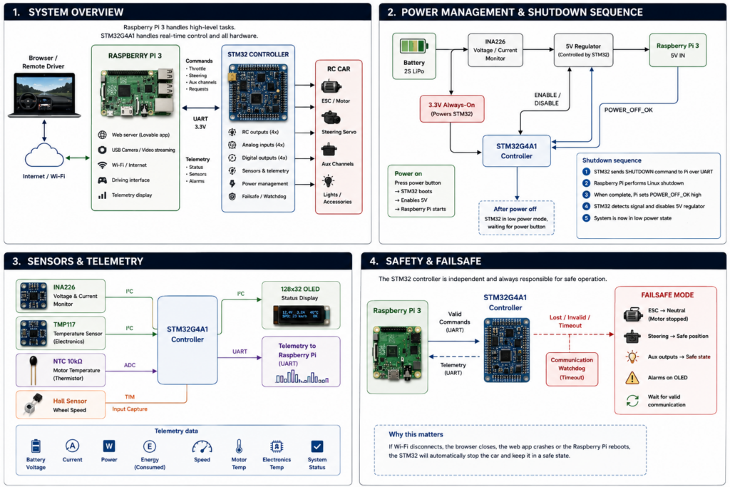
The idea behind this project is to build an internet-controlled RC car using a Raspberry Pi 3 for the high-level stuff and a dedicated STM32 microcontroller for controlling the actual hardware.
The Raspberry Pi handles the web interface, network connection and live video from a USB camera. The STM32 handles everything that needs predictable timing or should continue working even if Linux decides to have a bad day.
The project is still very much a work in progress, and both the hardware and software will probably change as I build and test it.
Two processors, two different jobs
The system is split between a Raspberry Pi 3 and an STM32G4A1.
The Raspberry Pi is basically the brain responsible for communication with the outside world. It runs the web server, streams video from the camera and handles commands coming from the browser.
The STM32 sits between the Raspberry Pi and the RC hardware. It generates the signals for the ESC and steering servo, reads sensors and takes care of power management and safety.
The two communicate over a simple UART connection.
This separation also means that Linux doesn’t have to generate timing-sensitive RC signals directly.
The STM32 controller board
I’m designing a custom controller board around an STM32G4A1.
The board currently has four RC outputs. Two will be used for throttle and steering, leaving another two available for future functions.
It also has four general-purpose analog inputs and four MOSFET-switched outputs that can be used for things like lights or other accessories.
The RC outputs are generated using the STM32’s TIM1 hardware timer, so the pulse timing isn’t dependent on software timing or whatever the Raspberry Pi happens to be doing.
There’s also a small buzzer for status and warning sounds.
Raspberry Pi 3
The Raspberry Pi 3 handles the parts of the project where Linux is actually useful.
It takes care of Wi-Fi, the web server, the USB camera and video streaming. It also acts as the bridge between the person driving the car and the STM32.
Commands for throttle, steering and other functions are sent from the Pi to the STM32 over UART. Telemetry travels back over the same connection.
The Pi therefore doesn’t directly control the ESC or steering servo. It tells the STM32 what it wants the car to do, and the STM32 handles the hardware.
Web interface
The driving interface is being created using Lovable.
Once built, however, the web application runs locally on the Raspberry Pi rather than being hosted by Lovable. The Raspberry Pi is the actual web server inside the car.
The interface combines the live camera feed with a simple driving HUD. The plan is to show useful telemetry alongside the video, including speed, battery voltage, current consumption, power and motor temperature.
Driving commands from the browser are sent to the Raspberry Pi and then forwarded to the STM32.
This also means the core software for the car lives on the car itself. An external server isn’t required just to run the user interface.
Safety and failsafe
One reason I wanted a separate STM32 instead of letting the Raspberry Pi control everything directly is safety.
While the car is being driven, the Raspberry Pi continuously sends control messages to the STM32. The STM32 keeps track of when the last valid message was received.
If those messages suddenly stop because Wi-Fi disappears, the web application crashes, the Raspberry Pi reboots or something else goes wrong, the STM32 automatically enters failsafe mode.
The throttle is immediately returned to neutral and the other RC outputs are moved to predefined safe positions. The general-purpose outputs can also be configured to enter safe states.
The car will only accept normal driving commands again once valid communication has been restored.
This prevents one particularly unpleasant failure mode: losing communication while the last command happened to be full throttle.
Battery and current monitoring
I also want to know what’s happening electrically while driving.
An INA226 module measures the battery voltage and total current drawn by the car. It’s placed so that it measures the complete system rather than only the Raspberry Pi.
That means I can monitor how much current the motor pulls during acceleration as well as the consumption of the electronics.
The STM32 reads the INA226 over I²C and sends the measurements back to the Raspberry Pi for display in the web interface.
By integrating current over time, it should also be possible to estimate how much battery capacity has been used.
Temperature monitoring
There are two different temperatures I’m interested in.
A small digital temperature sensor on the controller board keeps track of the electronics temperature.
A separate 10 kΩ NTC thermistor can be attached directly to the motor. This is connected to one of the STM32 ADC inputs and gives a much better indication of how hard the motor is being pushed.
Eventually I’d like the STM32 to generate warnings if the motor gets too hot.
Measuring speed
Vehicle speed is measured independently using a Hall-effect sensor and a small magnet attached to a rotating part of the drivetrain.
Every time the magnet passes the sensor, the STM32 receives a pulse.
Instead of simply counting pulses in software, one of the STM32 hardware timers is used in input-capture mode to measure the exact time between pulses. From that and the wheel circumference and drivetrain ratio, the controller can calculate speed.
The result can then be sent to the Raspberry Pi and displayed directly in the driving HUD.
Local OLED display
There’s also a small 128 × 32 OLED connected directly to the STM32.
It’s mainly there because it’s incredibly useful while developing and debugging the car, but it also works as a simple local status display.
It can show things like battery voltage, current, motor temperature, speed, Raspberry Pi status and communication errors.
The OLED shares the same I²C bus as the INA226 and the onboard temperature sensor.
Because the display and STM32 are powered independently from the Raspberry Pi, the display can still show information while the Pi is starting up or shutting down.
Power management
The STM32 also controls power to the Raspberry Pi.
The STM32 itself is powered from a small always-on 3.3 V supply. The Raspberry Pi is powered through a separate 5 V regulator controlled by the STM32.
Pressing the power button wakes the controller and enables the Raspberry Pi supply.
Turning the system off is a little more interesting because simply cutting power to a running Raspberry Pi isn’t a particularly good idea.
Instead, the STM32 sends a shutdown command to the Raspberry Pi over UART. Linux then performs a normal shutdown.
Once shutdown has completed, the Raspberry Pi changes a dedicated POWER_OFF_OK GPIO. The STM32 detects this and finally switches off the 5 V regulator.
The STM32 can then enter a very low-power state while waiting for the next press of the power button.
Where the project is now
The project is currently in the hardware design and prototyping stage.
The basic architecture is now fairly well defined:
Raspberry Pi 3
handles networking, the web interface, camera and video.
STM32G4A1
handles real-time control, sensors, telemetry, power management and failsafe functions.
The browser
becomes the remote control.
There are still plenty of things to build, test and probably redesign along the way, but that’s also the interesting part of the project.